Energy Storage Technologies for Electric Applications
J. I. San Martín, I. Zamora, J. J. San Martín, V. Aperribay, P. Eguía
Integration of renewable sources in electrical networks has increased dramatically in recent years. However,
the power supplied by renewable energy sources is not as secure and easy to adjust to changes in demand, as the power
supplied by traditional power systems. As a result, storage devices are also integrated into the electrical network in order to ensure reliability and quality in the performance of the power system.
This paper presents the current state of development of various storage technologies proposed for use in electric power systems.
Thus, characteristic expressions, specific and comparative data (in technical and economic terms) are shown.
Introduction
Within the context of distributed generation, new energy sources rely mainly on renewable resources. However, energy production peaks do not always are in accordance to the energy demand. They can have large fluctuations in their daily, seasonal, annual or even multi-annual energy production cycles. Meanwhile, demand may vary throughout the day, week or year. Consequently, an energy reserve is required and energy storage devices can be very useful for an efficient energy management. Storage devices can store energy in off-peak hours and return it to the grid during peak hours.
This energy storage concept can allow a plant design for a fairly constant load operation, below peak demand. This process is known as peak leveling and it reduces significantly the high capital costs of power plants. There are many techniques for energy storage, based on virtually all forms of energy: electrical, mechanical, chemical and thermal. Moreover, storage technologies present different technical and economical criteria, which vary considerably, depending on the specific needs and applications [1]. Thus, these technologies can be divided into four categories, depending on the applications [2]:
- Low power applications in remote areas, mainly to supply transducers and emergency terminals.
- Medium power applications in remote areas, such as individual electrical systems and power supply to villages.
- Power-quality applications.
- Network connection application with peak leveling.
The first three categories are suitable for small scale systems, where energy could be stored as kinetic energy, chemical energy, compressed air, hydrogen, supercapacitors and superconductors.
The fourth category is suitable for large-scale systems, where energy could be stored as gravitational energy in hydraulic systems, thermal energy as latent and sensible heat, chemical energy in batteries or compressed air.
Parameters of Storage Technologies
The most relevant parameters that define these storage devices are:
- Storage capacity: defined as the amount of energy available in the storage device after completing the charging cycle. The discharge is often incomplete and therefore, storage capacity is defined based on the total energy stored, Wst, which is higher than the useful energy at a particular point of operation, Wut.
-
Energy available: determined by the dimensions of the generator-motor system used in the conversion
process of stored energy. Available power is usually expressed as a mean value. Besides, a peak value,
Pmax, is often used to represent the maximum power in charging and discharging cycles.
Moreover, the energy supplied in the discharge, or depth of discharge, is the ratio of energy released in relation to the amount of energy that can be stored. This value is usually indicated as a percentage. - Discharge time: defined by expression (1), [3].
- Efficiency: evaluated from the ratio between the energy released and the stored energy. Its value is given by expression (2).
- Durability: given by the number of times that the storage device can release energy, from the level for which it was designed. It is expressed as the maximum number of cycles, N, each one corresponding to a charge and discharge processes.
- Autonomy: Refers to the maximum time that the system can continuously release energy. It is defined by equation (3).
where:
τ(s): Discharge time, in s
Wst: Total energy stored, in Wh
Pmax: Maximum or peak power, in W
where:
η: Efficiency of storage technology
Wut: Useful or recoverable energy for a given point of operation, in Wh
where:
a: Autonomy, in s
Pdt: Maximum power discharge, in W
Characteristics of Storage Technologies
Nowadays, energy storage devices for Distributed Generation applications can be classified as:
- Mechanical systems: Flywheels.
- Pneumatic systems: Air compressors.
- Thermal systems: Water or oil heaters.
- Electric systems: Supercapacitors.
- Magnetic systems: Superconducting Magnetic Energy Storage.
- Electrochemical systems: Batteries, fuel cells.
The most frequently used systems are shown in figure 1. Additionally, they can be classified in direct and indirect storage. The former have fewer energy transformations, better energy efficiency and fewer devices than the later. In general, these devices should have: low discharge because of the storage in a short and long time; high efficiency; high lifetime under unforeseeable cyclic conditions and be able to deliver energy more or less quick; wide operating temperature range; low maintenance and be considered as non pollutant.
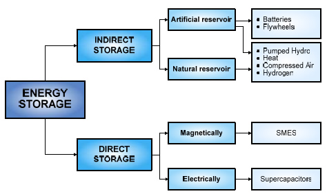
Fig. 1. Storage technologies classification
Following, the most relevant characteristics of different energy storage devices are presented.
A. Flywheel
Flywheels store electric power as kinetic energy, according to expression (4).
where:
I: Inertia momentum of the flywheel
ω: Angular speed
The maximum stored energy is limited by the tensile strength of the flywheel material [4]. Thus, the maximum specific energy density that can be stored in a flywheel is given by expression (5).
where:
Esp: maximum specific energy density
σm: Maximum tensile strength of flywheel material
ks: Shape factor
ρ: Density of the flywheel material
Besides, based on the material of the rotor, there are two types of flywheels:
- With advanced composite rotor, such as graphite or carbon-fiber. These materials provide high specific energy.
- With steel rotor. This type of flywheel allows traditional designs (with large diameters, low speed and low power and energy densities) and new highperformance flywheels.
Flywheels can provide an amount of energy in a relatively short time interval, so they can play an important role in primary frequency regulation. Figure 2 shows the operation diagram of a flywheel.
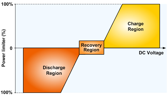
Fig. 2. Flywheel performance
B. Superconducting Magnetic Energy Storage (SMES)
A SMES unit consists of a large superconducting coil, maintained at cryogenic temperature by a cryostat containing liquid helium or nitrogen. The energy stored in the coil, E, is given by expression (6).
where:
L: Inductance coefficient
I: Current
With this technology, very small time response (<<1 s) with high power peaks can be obtained. In addition, this device provides high efficiency, since the superconducting coil has virtually no Joule losses. Only electronic converter losses are considered.
Figure 3 shows the structure of a storage system using superconducting coils [5]. This SMES system uses a signal conditioning device for connecting the DC bus of the coil with the AC bus, allowing its charge and discharge.
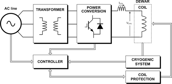
Fig. 3. Superconducting magnetic energy storage system
C. Supercapacitor
These devices have an operating principle similar to a traditional capacitor. However, their capacity and discharge current are much higher. The main difference compared to conventional capacitors is based on two aspects:
- Energy is stored at the interface between a porous conductive electrode and a liquid electrolyte ionic conductor.
- The surface is greatly increased due to the very high porosity of the electrode.
Supercapacitors are used for voltage drop compensation in weak networks, allowing a very intense peak power. Efficiencies of about 90% can be achieved in the complete cycle of charging and discharging.
To analyze the behavior of these devices, supercapacitors can be represented by an equivalent electric circuit [6]. Figure 4 shows a supercapacitor model consisting of RC elements.
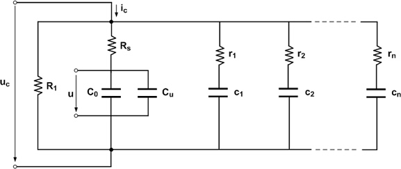
Fig. 4. Model of a supercapacitor
The parameter analyzed in this model is the supercapacitor capacity, C, which defines its behavior and the energy stored. This capacity is not constant and depends on the voltage across its terminals. For that reason, capacity is modeled as a constant value, C0, in parallel with a conventional capacitor, Cu, showing a linear dependence on voltage, u, as shown in expressions (7) and ( 8).
In addition, resistance Rs represents voltage drops during charge and discharge and resistance R1 loss of charge when the device is in stand-by. Finally, the 'n' parallel RC circuits represent the relaxation phenomenon produced inside the supercapacitor due to diffusion of charges.
As an example of application, Figure 4 shows a supercapacitor integrated in an electrical microgrid [7].
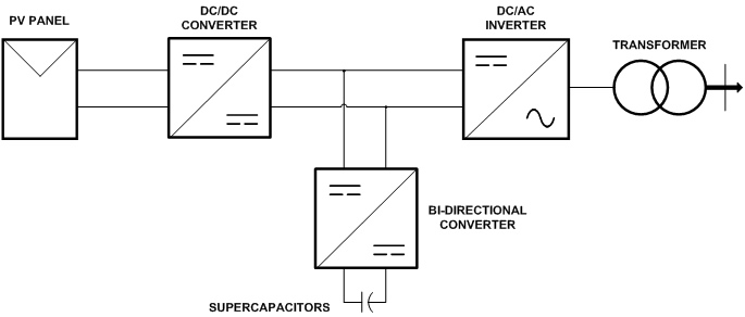
Fig. 5. Supercapacitor in an electrical microgrid
D. Battery Electric Storage System (BESS)
Batteries are devices that convert chemical energy into electrical energy, by oxidation and reduction of their materials. They consist of a base unit, which is combined with other, in series or parallel, for obtaining the required levels of capacity or voltage.
Many types of electrochemical batteries have been developed, which can be used in electric power systems, including: lead acid, flooded type, valve regulated, sodium sulfur, lithium ion, metal air, flow batteries, vanadium redox, zinc bromine, nickel cadmium, etc.
These batteries have some specific parameters that characterize them. The following can be pointed out:
- The open circuit voltage, measured when the battery is not working.
- Capacity in Ah. It is the amount of current that can be supplied in a specified discharge.
- State of charge (SOC). Specifies the percentage of battery capacity available with respect to its nominal value.
- Maximum discharge current of the battery.
- State of health (SOH). Reflects the general condition of a battery and its ability to deliver the specified performance compared with a fresh battery.
- State of performance (SOF). Indicates the battery capacity to perform some specific parts of the working cycle.
- Depth of discharge (DOD). This parameter represents the amount of energy that can be extracted from a battery and it is expressed as % of the total battery capacity.
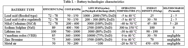
Table I shows the most relevant properties of these batteries [8].
Table I. – Characteristics of battery technologies
E. Pumped Hydroelectric Energy Storage (PHES)
This is a well known technology that performs in a reverse way than the traditional hydropower generation plants. Thus, power in off-peak hours is used to pump water to a reservoir located at higher altitude. During peak hours the water stored in the upper reservoir passes through a hydraulic turbine producing electricity that is fed into the grid. The transition time between the generation and accumulation states should be short to respond to sudden changes in power requirements. The main advantages are the low cost of energy and the possibility of frequency regulation.
In this storage technology, the ratio of energy supplied to the network and the energy consumed while pumping must be considered to evaluate the overall efficiency of the energy storage system. The energy used to pump a water volume, V, to a height, h, with a specific pumping efficiency, ηp, is given by equation (9). The energy supplied to the electrical network by a generator of efficiency ηg can be obtained by equation (10).
As example of this technology, Figure 6 shows a renewable power system, which includes a set of wind turbines, water storage, hydropower generation and interconnection to the electrical network. This arrangement allows transmitting power from renewable sources to final users [9].

Fig. 6. Hybrid wind-hydro power plant
F. Compressed Air Energy Storage (CAES)
In this storage technology, the air is compressed and stored in reservoirs, aquifers or underground cavities. The stored energy is released during periods of peak demand, expanding the air through a turbine. When air is compressed for storage, its temperature will increase according to expression (11).
where:
T: Temperature
P: Absolute pressure
K: Polytropic index of the irreversible compression.
Subscripts 1 and 2: indicate the initial and final state of compression, respectively.
The heat generated can be retained in the compressed air or in another heat storage medium. This way, heat can be returned to the air before its expansion in the turbine. This method is called adiabatic storage system and achieves a high efficiency.
However, if the heat generated in compression is lost, additional heat must be supplied to the air by burning a fuel, forming a hybrid storage system. In general, for a given pressure ratio, the work of the turbine is directly proportional to the absolute temperature of admission.
Furthermore, CAES systems are based on two stages of expansion. The first stage represents the work of the first turbine which expands the air inlet at pressure p1, until the inlet pressure of the second turbine, p2. Similarly, the second stage represents the work resulting from expansion from pressure p2 to barometric pressure, pb.
Finally, electrical performance of CAES is evaluated through the estimation of electricity that can be generated per unit of volume of the storage tank, Egen/Vs. Egen is the power produced by the turbine, given by expression (12), [10].
where:
m·T: Air mass flow rate.
WCV,TOT: Total mechanical work, per unit mass, generated in the process.
t: Time required to empty completely the air tank, at full output power.
ηM : Mechanical efficiency of the turbine.
ηG : Electrical efficiency of the generator.
As example, Figure 7 shows a CAES system that operates with the excess generation of a wind farm [10-12]. This system operates in the same way as a conventional gas turbine, but compression and expansion operations are independent and they occur at different times.
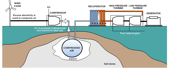
Fig. 7. Possible configuration of a CAES system
Comparative Analysis of Storage Technologies
To be highly efficient, storage technologies need to be adapted for each application type: medium power networks in remote areas, interconnected networks with distributed generation, etc. [2]. Besides, the type of power production, through renewable or fossil resources, must be considered. Thus:
- Considering low power permanent applications in which the key phenomenon is the possible selfdischarge, lithium-ion batteries are presented as the most successful technology.
- In small electrical systems, up to few kWh, located in isolated areas and based on renewable resources, the most important characteristic is autonomy. Based on this, and as a compromise between electrical performance and cost, lead-acid battery can be considered the most appropriate technology.
- For electrical systems up to a few hundred kWh, leadacid battery is still the best, better than lithium-ion battery, because of the cost. Other storage technologies can be small compressed air and flow batteries, but they are less efficient or more costly.
- In electrical systems of many MWh, high energy storage technologies are required, such as large compressed air and flow batteries.
- Regarding power-quality applications, the most important characteristics are energy discharged speed and cycling ability. In this sense, flywheels and supercapacitors are the most appropriate.
- Finally, certain technologies must be considered to meet the storage needs from energy intermittent resources. In this context, pumping of water for largescale systems and SMES for small-scale systems can be highlighted.
Following, some figures are presented that compare different aspects of storage technologies. These aspects cover topics such as: range of applications, efficiencies, lifetime, costs, mass and volume densities, etc.
Figure 8 shows the application range of different energy storage technologies, based on energy stored and power output [13]. Figure 9 shows the most appropriate storage technology for the three most important operational categories: power quality, power bridging and energy management [14].
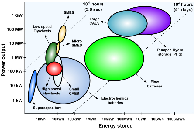
Fig. 8. Ranges of application of storage technologies
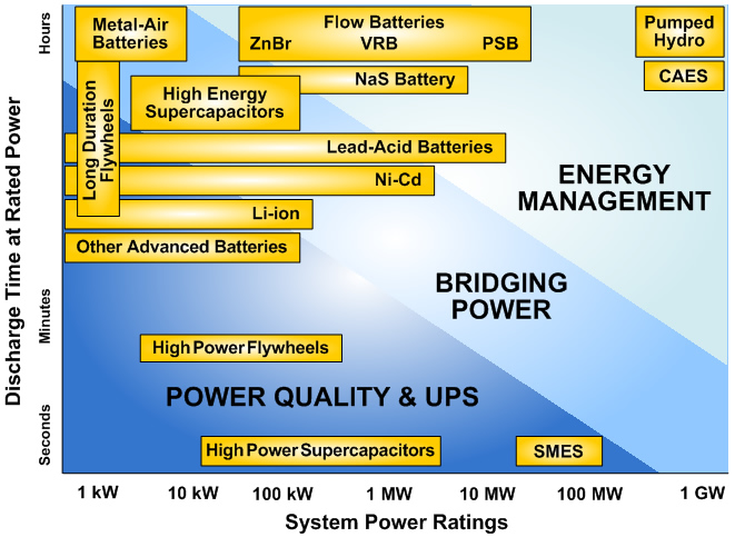
Fig. 9. Storage technologies capacity
Also, efficiency and lifetime are two parameters to be considered, as they affect the overall storage costs. Figure 10 shows the characteristics of different storage technologies in relation with efficiency and lifetime [14].
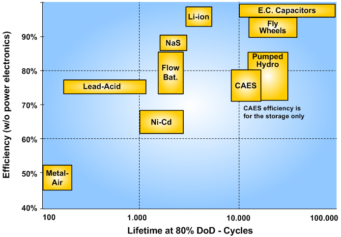
Fig. 10. Efficiency and lifetime of storage technologies
Moreover, costs associated with each type of storage and the total cost impact of energy production are also important economic parameters. Figure 11 shows the investment costs of various energy storage technologies per unit energy [14].
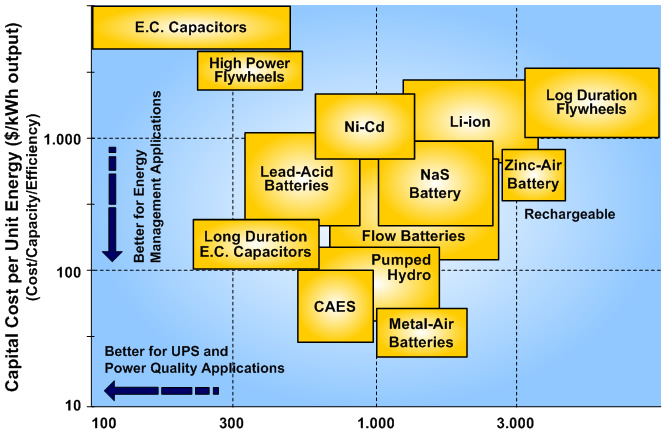
Fig. 11. Investment costs of storage devices
Additionally, cost per cycle is a suitable parameter for evaluating the cost of a storage system, designed for applications with frequent charging and discharging cycles. Figure 12 shows the cost of various technologies, taking into account their durability and efficiency [14].
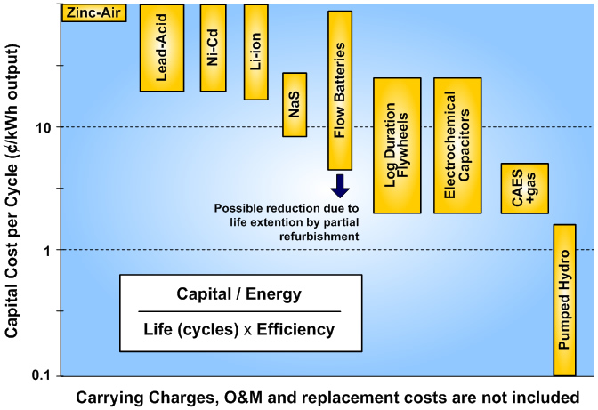
Fig. 12. Investment costs of storage technologies for each charge-discharge cycle
Finally, the different storage technologies can be classified based on the availability of energy and maximum power, per density of volume or mass. This comparison is particularly important for power transmission, portable and remote applications. Figure 13 shows a comparative of different storage technologies based on mass and volume densities [14].
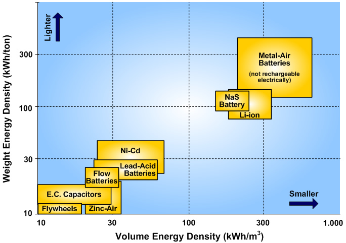
Fig. 13. Mass and volume densities of storage technologies
Conclusions
Renewable energies, like wind or solar, have a variable electricity output and, consequently, most of the time cannot be used directly in covering the energy demand. They can produce energy when it is not needed and, when needed, the generation output cannot be enough. Therefore, renewable energy sources can have a limited contribution to power generation.
Energy storage technologies are a solution to this problem, because they can be integrated in the power system structure with different renewable energy sources. These technologies can maximize the contribution of renewable energy, promoting efficient use of the same, facilitating the equilibrium between generation and demand, reducing emissions of greenhouse gases, reducing network connection costs and improving operation and control of the power system.
This paper presents the most relevant properties of energy storage technologies currently being developed in the design of power systems. In this sense, it describes the most important parameters that characterize the behavior of different technologies and a comparative analysis, which covers different aspects.
Acknowledgement
The work presented in this paper has been supported by the Basque Government (Ref. IT532-10) and by the Regional Council of Guipuzcoa
References
- J.I. San Martín, I. Zamora, J.J., V. Aperribay, P. Eguía, "Hybrid fuel cells technologies for electrical microgrids", Electric Power Systems Research, Vol.80, pp.993-1005, 2010.
- H Ibrahim, A Ilinca, J. Perron, "Energy Storage Systems. Characteristics and Comparisons", Renewable and Sustainable Energy Reviews, Vol.12, pp.1221-1250, 2008.
- G. Robin, M. Ruellan, B. Multon, H. Ben Ahmed, P.Y. Glorennec, "Solutions de stockage de l'énergie pour les systèmes de production intermittente d'électricité renouvelable", Systèmes et applications des technologies de l'information et de l'énergie, (UMR 8029 CNRS), ENS Cachan (France), 2004.
- H. Liu, J. Jiang, "Flywheel energy storage - An upswing technology for energy sustainability", Energy and Buildings, Vol.39, pp.599-604, 2007.
- H.Y. Jung; A.R. Kim, J.H. Kim, M. Park, J.K. Yu, S.H. Kim, K. Sim, H.J. Kim, K.C. Seong, T. Asao, J. Tamura, "A Study on the Operating Characteristics of SMES for the Dispersed Power Generation System", IEEE Transactions on Applied Superconductivity, Vol.19, pp.2028-2031, 2009.
- P. Barrade, "Energy storage and applications with supercapacitors", Ecole Polytechnique Fédérale, Lausanne Switzerland), 2003.
- PJ Binduhewa, A.C. Renfrew, M. Barnes, "Ultracapacitor Energy Storage for MicroGrid Micro-generation", Power Electronics, Machines and Drives Conference, PEMD, pp.270-274, York (UK), 2008.
- K.C. Divya, J. Østergaard, "Battery energy storage technology for power systems - An overview", Electric Power Systems Research, Vol.79, pp.511-520,2009.
- J. Anagnostopoulos, D. Papantonis, "Pumping station design for a pumped-storage wind-hydro power plant," Energy Conversion& Management, Vol.48, pp.3009–3017, 2007.
- S. Succar, R.H. Williams, "Compressed Air Energy Storage: Theory, Resources, and Applications for Wind Power" Princeton Environmental Institute Report, 2008.
- Ridge Energy Storage & Grid Services L.P. "The Economic Impact of CAES on Wind in TX, OK, and NM", Final Report, Texas State Energy Conservation Office. 2005.
- E. Mazharia, J. Zhaoa, N. Celika, S. Leea, Y.J. Son, .L Heada,"Hybrid simulation and optimization-based design and operation of integrated photovoltaic generation, storage units and grid", Simulation Modelling Practice and Theory, 2010.
- Emerging Energy Storage Technologies in Europe. Rapport Frost& Sullivan, 2003.
- Electricity Storage Association. www.electricitystorage.org.
International Conference
European Association for the Development of Renewable Energies, Environment and Power Quality (EA4EPQ)
International Conference on Renewable Energies and Power Quality (ICREPQ'11)
Las Palmas de Gran Canaria (Spain), 13th to 15th April, 2011